Applications:
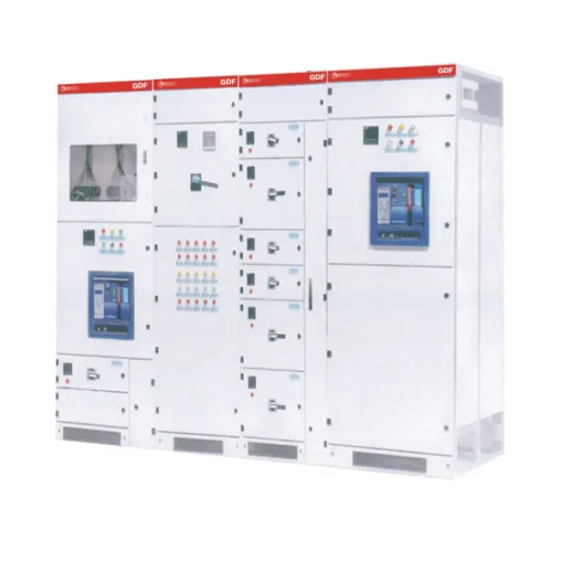
The GCK low-voltage withdrawable switchgear is widely used in power plants, metallurgical rolling mills, petrochemical industries, light industry and textile, port terminals, hotels in high-rise buildings and other places. It is used for power distribution and centralized motor control in the power supply systems with three-phase four-wire or five-wire system of alternating current, voltage of 380V or 660V, frequency of 50Hz and rated current of 5000A or below.
The GCK is a high-grade low-voltage switchgear assembled after passing comprehensive type tests and obtaining CCC certification. Its design complies with the following standards: the national standard GB7251.1 – 2005 “Low-voltage switchgear and controlgear assemblies”, and the international standard IEC60439.1 – 1992 “Low-voltage switchgear and controlgear assemblies”.
Model Meaning:
Numbering system for main circuit schemes, withdrawable and enclosed switchgear.
Normal Service Conditions:
The ambient air temperature shall not be higher than +40 °C and not lower than -5 °C. The average temperature within 24 hours shall not be higher than +35 °C. The relative humidity shall not exceed 50% when the temperature is at a relatively high +40 °C. At lower temperatures, a relatively higher relative humidity is allowed, for example, 90% at +20 °C. The air shall be clean, free of corrosive and explosive gases, and free of conductive dust and dust that can damage insulation. It shall be installed vertically in places without significant shaking and impact vibration, and the inclination shall not be greater than 5 degrees. The altitude shall not exceed 2000 meters. The switchgear is suitable for transportation and storage within the temperature range from -25 °C to +55 °C, and shall not exceed +70 °C within a short period (not exceeding 24 hours). If the user cannot meet the above conditions, they should consult with the manufacturer.
Main Technical Parameters:
Rated insulation voltage: 660V / 1000V
Rated working voltage: 400V / 660V
Rated working voltage of auxiliary circuits: AC 380V, 220V, DC 110V, 220V
Rated current of busbars: 1000A, 1250A, 1600A, 2000A, 2500A, 3200A, 4000A, 5000A
Rated short-time withstand current of busbars: 50kA, 80kA (effective value) for 1 second
Rated peak withstand current of busbars: 105kA / 0.1s, 140kA / 0.1s, 176kA / 0.1s
Rated current of branch busbars: 630A, 1000A, 1250A, 1600A
Rated short-time withstand current of branch busbars: 30kA, 50kA (effective value) for 1 second
Rated peak withstand current of branch busbars: 63kA, 105kA / 0.1s
Enclosure protection grade: IP30, IP40
Busbar arrangement: Three-phase four-wire system, Three-phase five-wire system
Operation mode: Local, Remote, Automatic
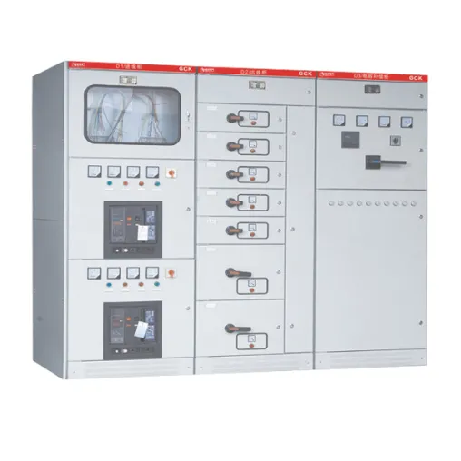
Classification of Switchgear
• Incoming Cabinet
• Bus – Tie Cabinet
• Feeder Cabinet
• Motor Control Cabinet
• Power Supply Transfer Cabinet
• Power Factor Compensation Cabinet
Structural Features
The basic frame of GCK is a combined prefabricated structure. All structural parts of the frame are galvanized and spray – painted, and are connected to each other by screws to form the basic frame. Then, according to requirements, parts such as doors, baffles, partitions, drawers, mounting brackets, busbars, and electrical components are added to assemble a complete control center cabinet. This cabinet has the following structural features:
Frame
The frame is assembled from C – shaped profiles. Frame parts and special supporting parts are supplied by our company to ensure the accuracy and quality of the cabinet body. The forming dimensions, hole – opening dimensions, and equipment intervals of components are modularized (Internal structural parts are galvanized. The top cover of the cabinet is detachable, and lifting rings are installed at the four corners of the cabinet top for lifting and transportation. The frame is divided into three isolated compartments: the busbar chamber, the functional unit chamber, and the cable chamber, which can prevent the spread of accidents.
Functional Unit (Drawer Part)
The height module of the drawer unit is 200mm, and it is divided into five size series: 1/2 unit, 1 unit, 1.5 units, 2 units, and 3 units. The rated current of the unit circuit is 630A and below. (See the above figure for the appearance). E = 20mm, the same below. Each MCC cabinet can install a maximum of 9 one – unit drawers or 18 half – unit drawers. The operating mechanism is mechanically interlocked with the drawer. When the main switch is in the closed position, the drawer cannot be withdrawn. The operating mechanism of the drawer can be locked in the closed or open position with a padlock, which ensures safe maintenance of electrical equipment. The back of the functional unit is equipped with main circuit inlet and outlet plugs and auxiliary circuit secondary plugs. The functional unit compartments are separated by metal partitions. The drawer unit adopts a rotary propulsion mechanism with a three – position function, which is simple and reliable to operate.
The GCK drawer propulsion mechanism moves along the positioning parts in a spiral track, realizing the propulsion and withdrawal of the functional unit. During the process of propulsion and withdrawal of the functional unit, three – position display and mechanical interlock are achieved, and a micro – switch is equipped. Electrical interlock can be carried out in the test position.
Installation and Use
After the product arrives at the receiving place, first check whether the packaging is intact. If any problem is found, promptly notify the relevant departments of the contract to make a business record, jointly analyze the cause, make a visa, and handle the aftermath properly. For products that are not installed immediately, they should be placed in an appropriate place and properly stored according to the normal operating conditions and the requirements of the temporary storage regulations for electrical equipment.
The installation of the product should be carried out according to the installation schematic diagram. The foundation channel steel and the bolts for bolt – fixing are to be prepared by the user. When connecting the main busbars, if the surface is uneven due to transportation, storage, etc., it should be leveled before connection and tightening.
When the equipment is installed individually or in a row, the deviations of its verticality, cabinet surface flatness, and gaps between cabinets should meet the requirements specified in Table 1.
Serial Number Name Allowable Deviation (mm)
1 Verticality 3.3
2 Adjacent two cabinet tops, Tops of cabinets in a row, Adjacent two cabinet sides, Sides of cabinets in a row 2, 5, 1, 5, 2
3 Levelness –
4 Flatness –
5 Gap between cabinets –